Abstract
A
robust controller design to obtain output voltage regulation in a quadratic
boost converter with high DC-gain is discussed in this paper. The proposed controller
has an inner loop based on sliding mode control whose sliding surface is
defined for the input inductor current. The current reference value of the
sliding surface is modified by a proportional-integral (PI) compensator in an
outer loop which operates over the output voltage error. The stability of the
two-loop controller is proved by using the Routh-Hurwitz criterion, which
determines a region in the - plane where the closed loop system is always
stable. The analysis of the sliding mode-based control loop is performed by
means of the equivalent control method while the outer loop compensator is
derived by means of the Nyquist- based Robust Loop Shaping approach with the
M-constrained Integral Gain Maximization technique (RLS-MIGO). Robustness is analyzed
in depth taking into account the parameter variation related with the operation
of the converter in different equilibrium points. Simulations and experimental
results are presented to validate the approach for a 20 - 100 W quadratic boost
converter stepping-up a low DC voltage (15 – 25 V DC) to a 400 V DC level.
Index
Terms
1. Quadratic
boost converter
2. Robust
loop shaping
3. Sliding-mode
control
Circuit Diagram:

Fig.
1. Quadratic boost circuit configurations: a) ON-state; and b) OFF-state.
Expected Simulation Results:
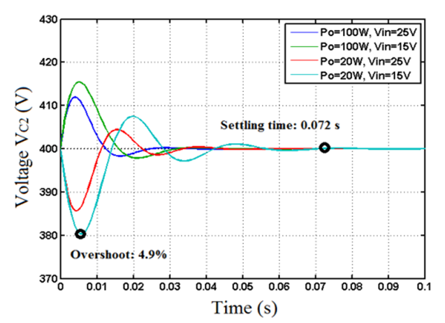
Fig.
2. Transient responses to output power step disturbances in the extreme values
of the converter operational range
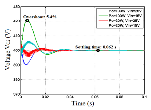
Fig.
3. Transient response to input voltage step disturbances in the extreme values
of the converter operational range.

Fig.
4. Transient response to a voltage reference step change in the extreme values
of the converter operational range.
Conclusions
A
complete description of a robust controller design obtaining output voltage
regulation in a high DC-gain quadratic boost converter involving a sliding-mode
current loop has been presented in this paper. The results show that this
control scheme has a satisfactory performance regulating the output voltage in
its overall operational range of output power and input voltage. The stability
of the complete system has been treated as local by using the Routh-Hurwitz
test constraining a stability region in the - plane which has been subsequently
used as a reference to synthesize the PI compensator using the RLS-MIGO method.
The stability and robustness of the overall system has been tackled by
considering the possible variations in the output load or in the input voltage
as parametric uncertainty. Several MATLAB simulations have been used to verify
the theoretical approach and the converter expected performance when coping
with important disturbances in the uncertain parameters. Moreover, experimental
results using simple electronic circuits are in good agreement with the
theoretical predictions and simulation results. The experiments have validated
not only the high DC-gain capability of the quadratic boost converter operating
with a hysteresis- based current controller but also the regulator robustness ,
ensured by the application of the loop shaping method in the PI synthesis. It
can be concluded that the RLS-MIGO method is compatible with the sliding-mode
approach providing an efficient solution to synthesize the proposed two-loop
controller for a high-order topology such as the quadratic boost converter.
Future works with the same converter will be devoted to the study of its
possible discontinuous and critical conduction modes together with the
associated design of an appropriate controller.
References
[1]
F Blaabjerg, Z Chen and S B Kjaer, “Power electronics as efficient interface in
dispersed power generation systems," IEEE Trans. Power Electron., vol. 19,
no. 5, pp. 1184-1194, Sept. 2004.
[2]
Q Li and P Wolfs, “A review of the single phase photovoltaic module integrated
converter topologies with three different DC link configurations," IEEE
Trans. Power Electron., vol. 3, no. 3, pp. 1320-1333, May. 2008.
[3]
S Lee, P Kim and S Choi, “High step-up soft-switched converters using voltage
multiplier cells,” IEEE Trans. Power Electron., vol. 28, no. 7, pp. 3379-3387,
Jul. 2013.
[4]
A Stupar, T Friedli, J Miniböck and J W Kolar, “Towards a 99% Efficient
Three-Phase Buck-Type PFC Rectifier for 400-V DC Distribution Systems,” IEEE
Trans. Power Electron., vol. 27, no. 4, pp. 1732-1744, Apr. 2012.
[5] Rockwell Automation, “Common DC bus:
Selection guide,” Publication DRIVES-SG001B-EN-P. Sep. 2005